|
|
|
Back to oil leakage Forward to replacing wheel bearings If the front wheels starts fluttering while driving or strict TÜV examiners resist on it, the kingpins have to be replaced. How this is done in a correct order, I found on the homepage of 'Der Entenschnabel' (see column 'links'). 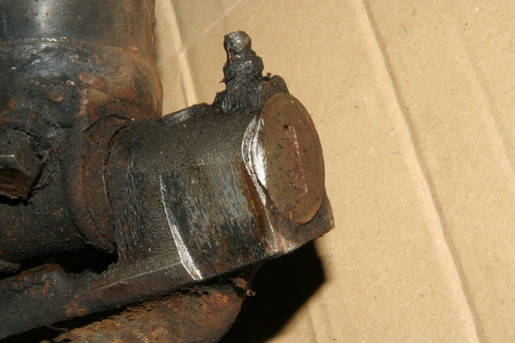 Firstly the cap at the lower end is to be unscrewed. It's bent at the edge to lock the device. 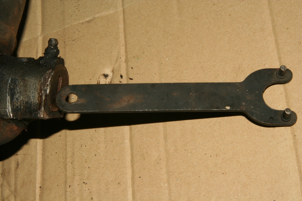 After treating with rust remover and bending off the edge, the cap can be unscrewed. The slot of this cap is rounded inward, so you can't use a normal screwdriver. I found out that the key of my Flex has accurately the correct form. Otherwise a flat iron of suitable dimensions can be rounded off. 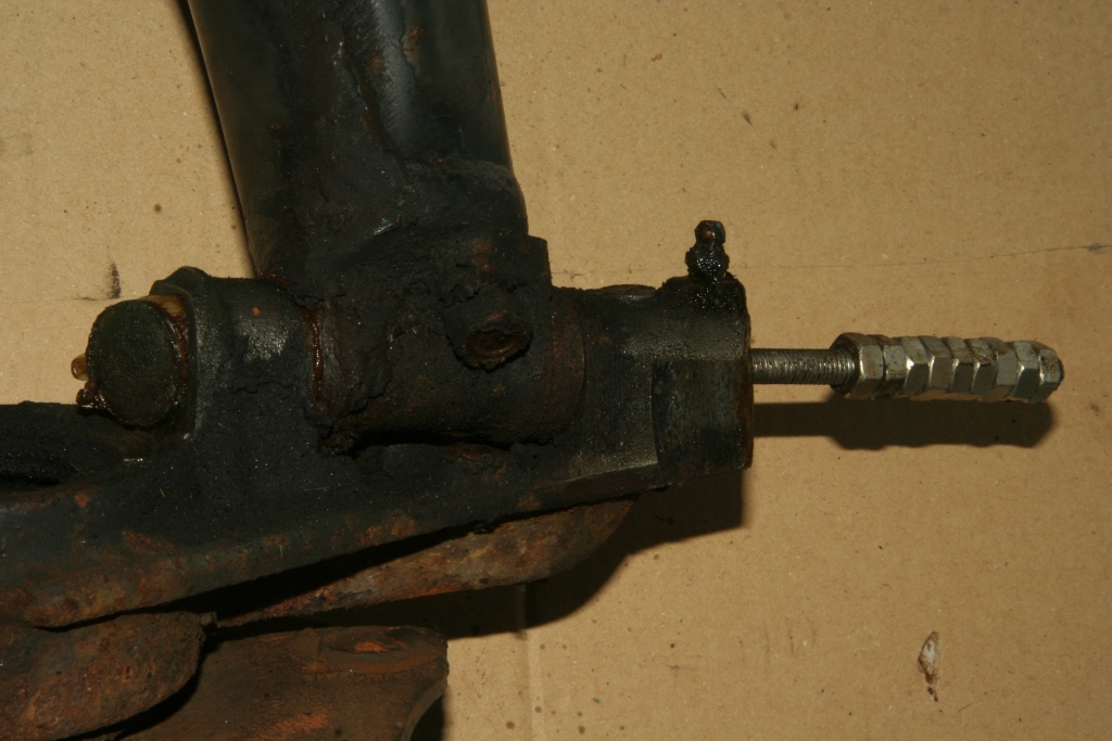 The upper cap was pressed-fitted. With a threaded rod M8 this can be removed from downside through the hollow kingpin with a hammer. 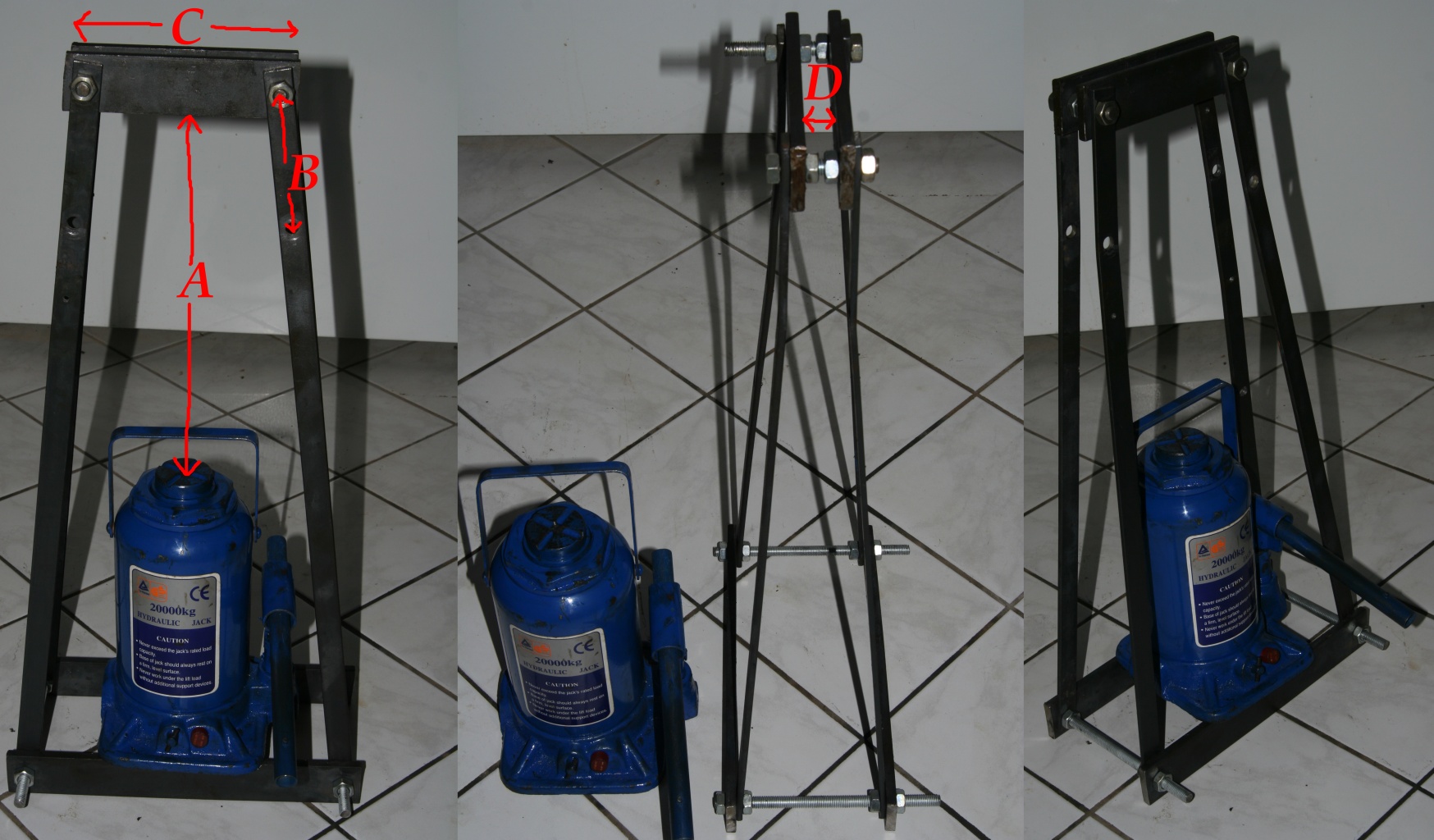 Now the kingpin is free to be removed. That can't be done with the thumb (only if you are a friend of Miraculix) and may never be done with a hammer! If you hit the pin using a thorn, it is expanded, i.e. it is flat-forged. You will destroy the drilling of the axle. Put the hammer aside! You need a jacking equipment (20t lifting capacity!) and a special frame. My construction is to be seen in the upper photo and consists of M10 threaded rods, as well as flat iron of the dimensions 40x8mm (transverse iron above and down) and 20x4mm (connections between upper and lower iron). Comment on the size of the flat iron: For my construction described here, I took the material lying somewhere in my garage. Later Terje from Norway pointed out that I probably never used the whole 20t of the hydraulic jack (sometimes it is better to do something than calculating too much). The maximum tension stress of iron is about 300N per mm². I used 4 flat irons of the dimension 20x4mm between the top and bottom. They are additionally weakened by drillings (each 10mm). So there remains an overall cross-sectional area of (20mm-10mm) * 4mm * 4 = 160mm², which holds 160mm² * 300N/mm² = 48000N, according to 48000N / (9.81m/s²) = 4.89 tons compressive force. So if you go to play it safe you should use flat iron with the dimensions 30x8mm for the construction. Thank you Terje for the correction. A=30cm (distance lower edge of the upper flat iron to the upper edge of the brought in jacking equipment stamp), B=10cm (distance of the upper drillings of the upper flat irons) C=16cm (length of the upper flat irons) D=2cm (gap between the two upper flat irons). The remaining dimensions depend on the dimensions of the jacking equipment. The lower iron should be broad enough, in order to be able to shift the jacking equipment to the left and on the right and there should be enough space, in order to be able to pump it up. The lower rods should be long enough so that the jacking equipment isn't completely on the edge of the lower flat irons. This must be shifted sometimes for adjusting. 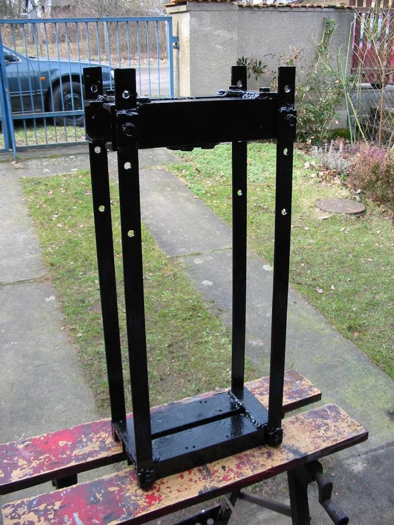 Much more robust is Hartmut's construction. In his mind, my frame was too wobbly (That's right - four hands are better than just two while operating my construction). The stability should be no problem when using the design of the photo above. 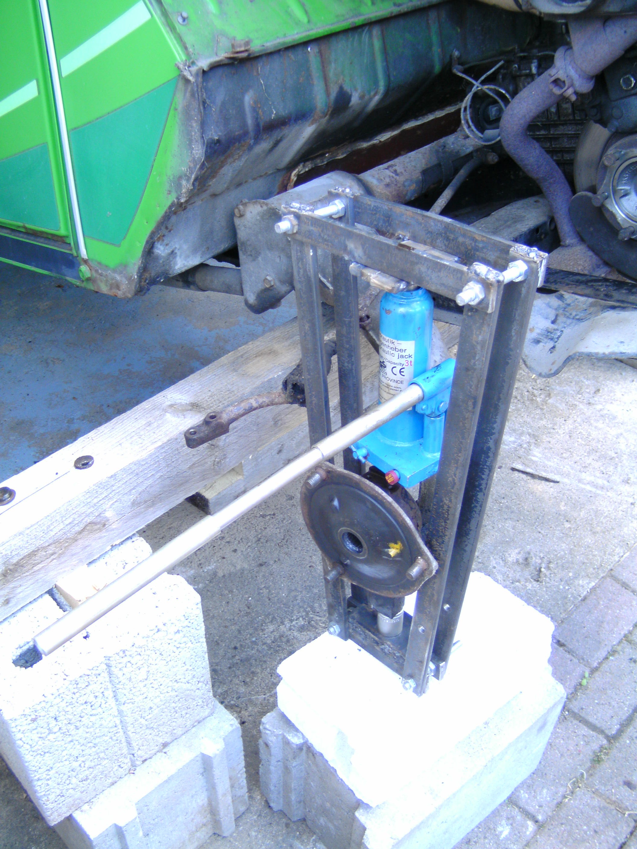 Dominik's version (pushing from the top) looks very solid, too. 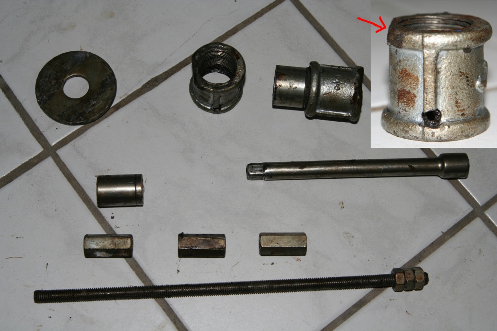 For pushing out the pin following tools are needed: (1) Grommet, not too thinly, for allocating the pressure. (2) Coupling sleeve 3/4inch for water installation. Cut the edge as shown at the photo. (3) One more coupling sleeve, with screwed in piece of water pipe. (4) 14mm (or other suitable) nut from the ratchet box. (5) Suitable extension for the nut. (6) 3x threaded rod link for M10 threaded rods. (7) Threaded rod M8 with 3 nuts at one end. 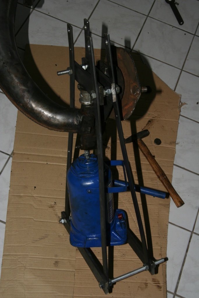 The M8 threaded rod with the 3 nuts serves with the first pulling as tool. Since the whole construnction does not stand straight on the soil, four hands are better than two with this working procedure. If you gave little pressure with the jacking equipment, the adjustment can be corrected by means of slight hammer blows. Now remove the pin with jacking equipment and M8 threaded rod remove for the first stage, until the threaded rod has 'disappeared'. Now lower the jacking equipment, put additionally the M10 rod link on the M8 rod (they fit through the camps of the kingpin with their outside diameter) and push the next stage. With the second and third M10 thread link proceed in the same way. 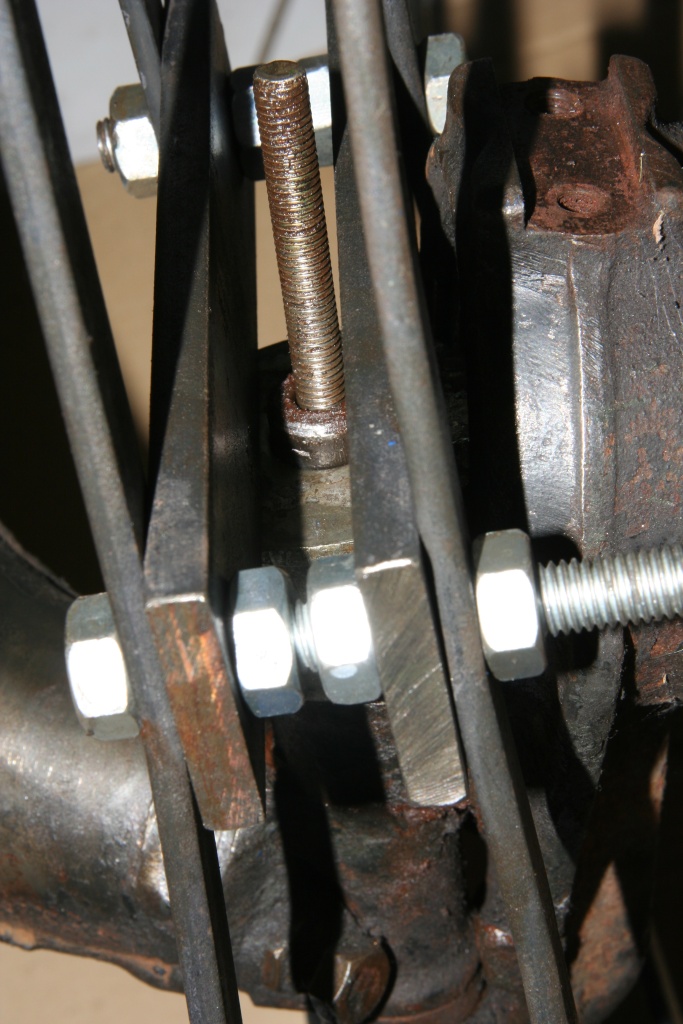 After the second stage of pushing you can see the pins coming out above. Be sure that they fit through the grommet! 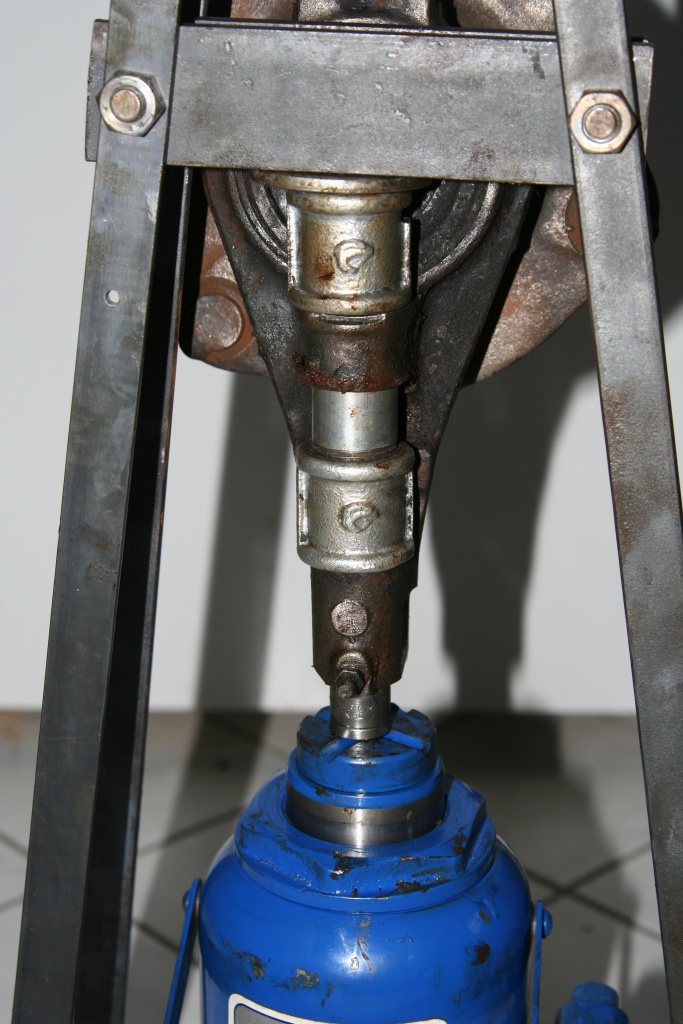 After the pins, the camps have to be pulled out. In addition now the sleeve with the screwed pipe is needed. This is putten into the knuckle and the pipe is somewhat unscrewed, until the sleeve blocks centrically. The sleeve should point downward, so that the camp fits when squeezing out. This prevents the knuckle from beeing bent and shold not be forgotten!. The sanded off edges of the sleeves point to the rear. As pushing tool the 14mm nut is used in the first step. This one had the suitable outside diameter (only somewhat smaller than the diameter of the camps). In the second step with the lower camps the nut was threaded at the M8 rod with the 3 nuts and pushed again. 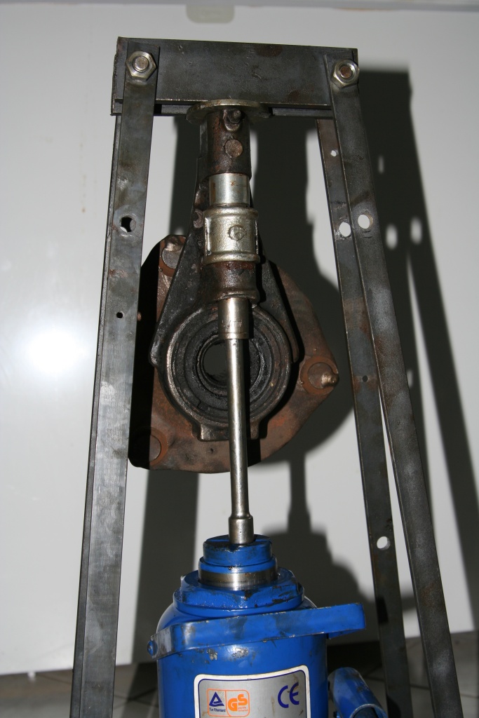 After the lower camps now the upper copies are squeezed out. In addition the subframe is converted. The upper flat irons must be attached now at the upper drillings (2). For the previous pushing, position 1 was more favorable, in order to keep the levers smaller. As pressing tool again the 14mm-nut serves, this times however put on a suitable extension. The whole construction must be aligned particularly straight-lined. The sleeve with the pipe points to the camp again. 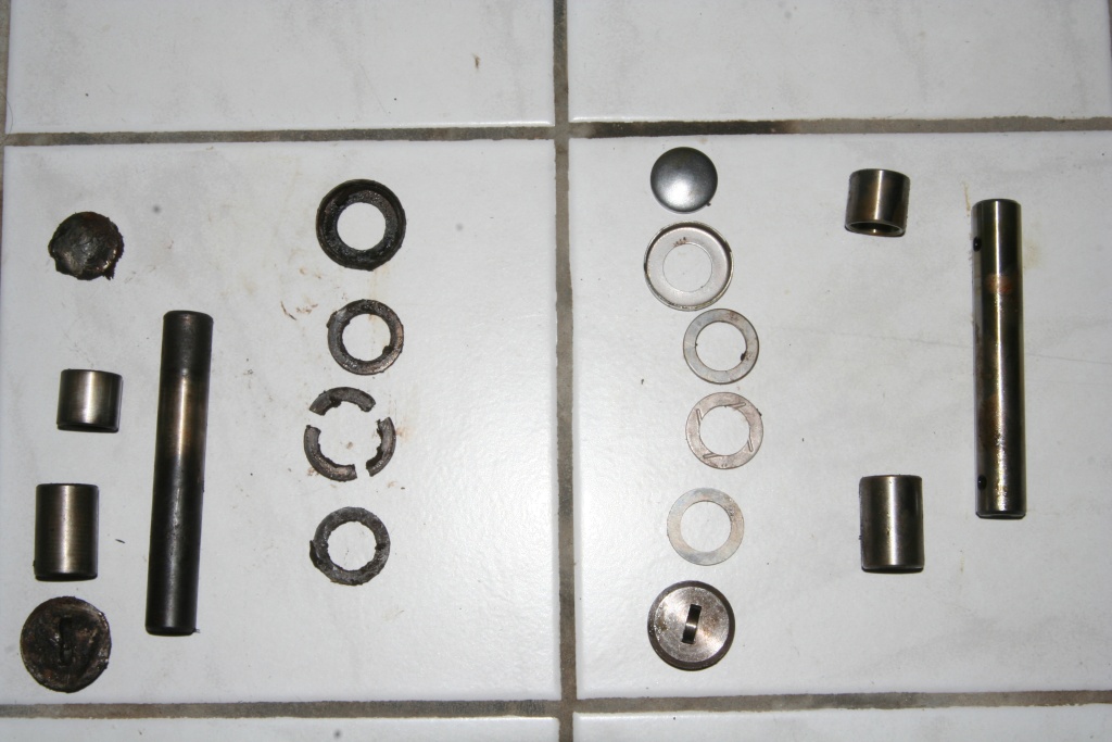 Now the old parts are out and can be replaced by new ones. I ordered the complete set with new camps and caps. Assembly of the kingpins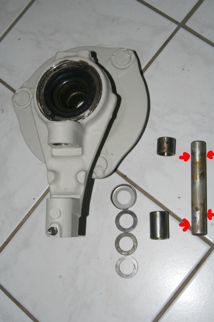 The pins are drilled in different heights at the bottom. At the top these drillings are at the same height (red arrows). The lower bearing ist bigger, the smaller one belongs to the top. The grommet with the crease belongs between the two normal ones. The casing belongs to the top.  First I pressed in the lower bearing. As guidance i used the old pin an an old bracket aditionally to the 14mm wrench.  The bearings have to be flusch with the edge of the axle leg. Therefor I used a grommet between bearing and wrench (red arrow) and pressed till block. 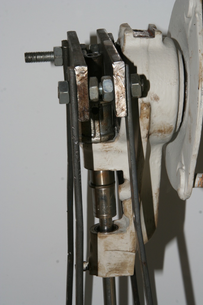 At the picture of the upper bearing you can see the old pin used as guidance.  Put the well greased grommets + cap on the axle leg and position it on the axle. Clean all surfaces well, because it fits very strong. Now you can press in the kingpins with the help of the M8 thread rod. The pins have to flush with the upper edge of the upper bearings.  Next the screw caps can be mounted. Clean the threads well. It's a good idea to use a screw tap M22 x 1mm.  The screw caps have to be screwed in completely. Then bend the edge at the accordant point to lock it. 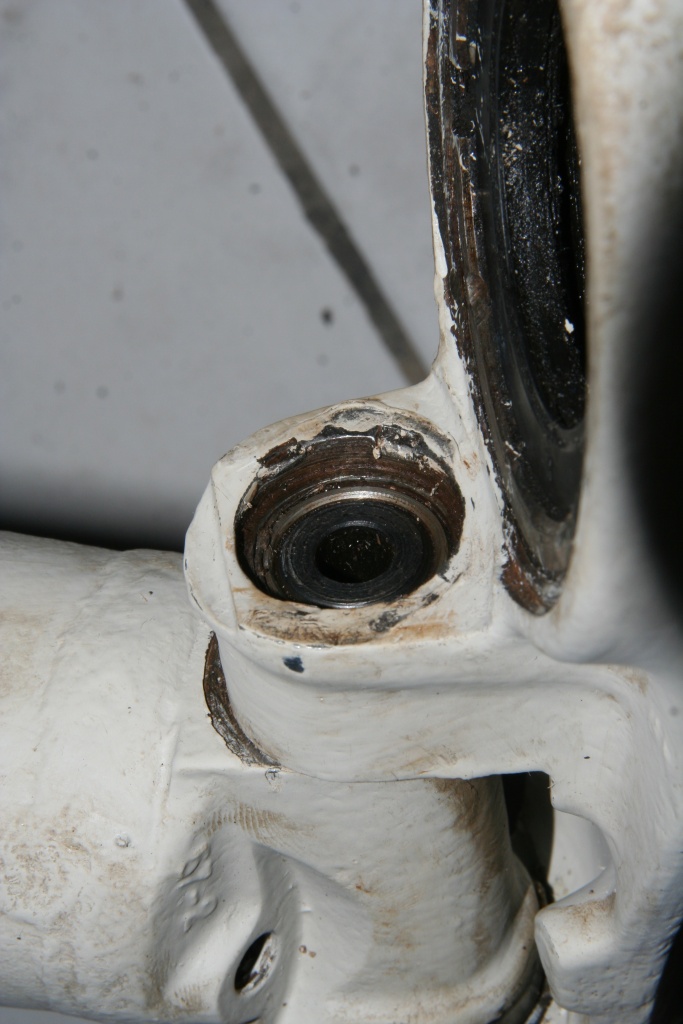 The top of the axle leg has to be cleaned also and the old lock punches have to be removed. 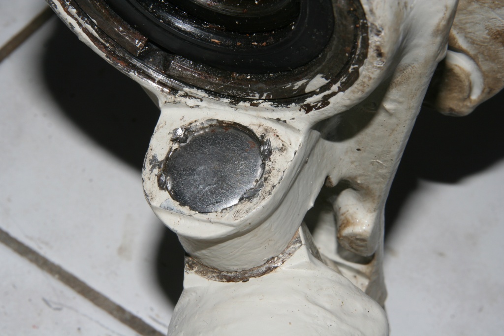 The upper caps can be mounted now with hammer blows on the center of the cap. So the caps are bend outwards and the bearings are closed. Three to four lock punches fix the caps at this position. Now use the grease gun to lubricate the kingpins. The grease should escape between the axle leg and the axle - not at the caps. Otherwise use some more hammer punches at the middle of the cap to seal. Back to oil leakage Forward to replacing wheel bearings |