|
|
Back to engine + gear Forward to breakes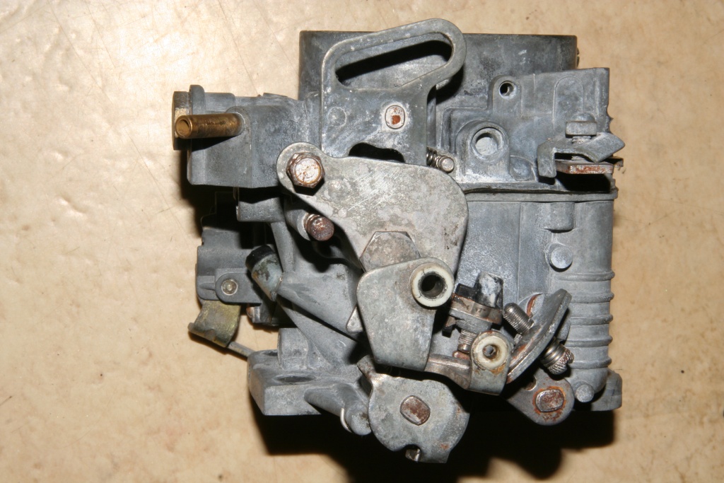 Driver's side - the left side of the photo points to driving direction. 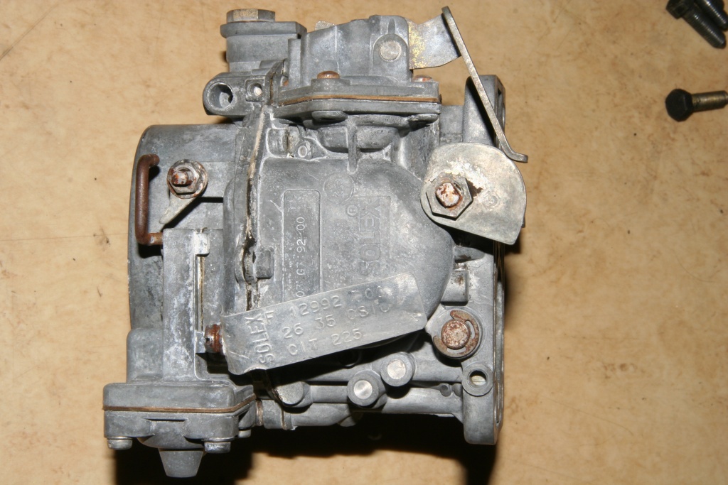 Curbside - the upper side of the photo points to driving direction. 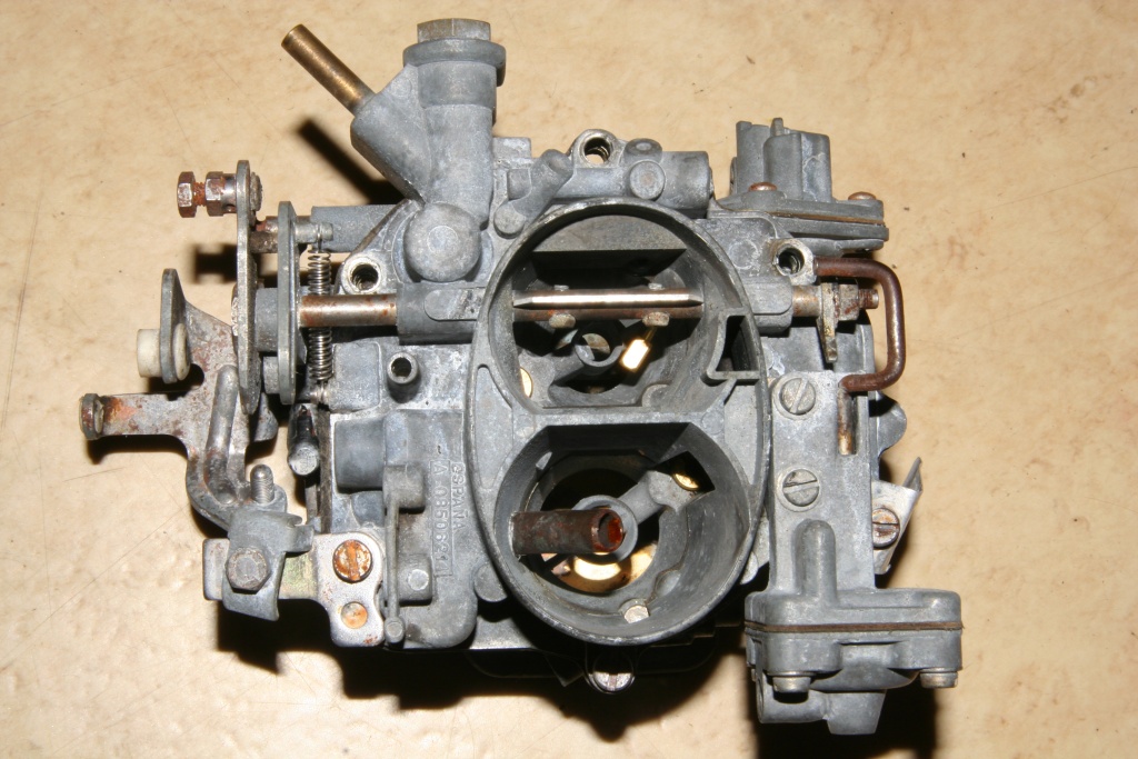 Top side - the upper side of the photo ponits to driving direction.  Lower side - the lower side of the photo points to driving direction. 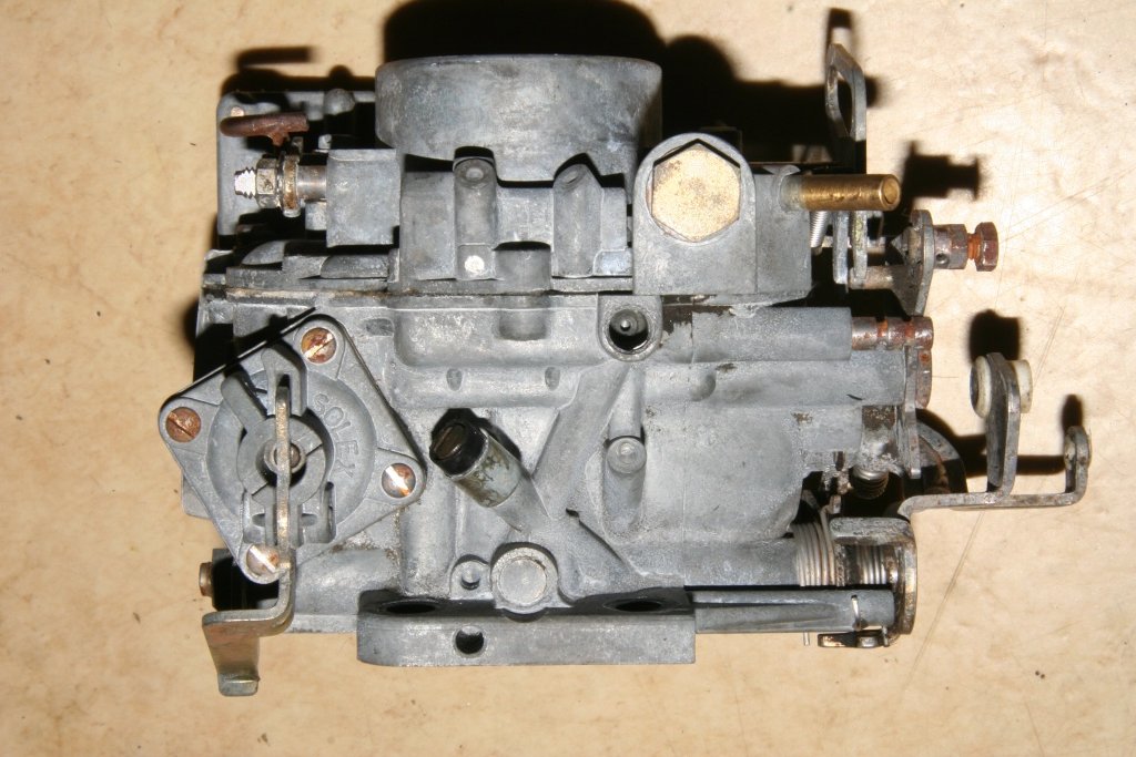 Front side. The arrow marks the place of nozzle No. 6 (see photo further below). Those nozzle regulates the mixture while the engine is in idle. So if your engine always stops running while the throttle is (nearly) closed, have a closer look at this place of the carburetor. Maybe you have lost this nozzle. Left down the accelerator pump can be seen. If the accelerator pedal is stepped, some gasoline is injected into the carburetor. If the duck accepts acceleration badly, it can be because of this construction unit. Pushing the lever of this pump indicates if the gasoline supply still works correctly. You can notice a resistance during manual operation and hear also the injection of the gasoline. 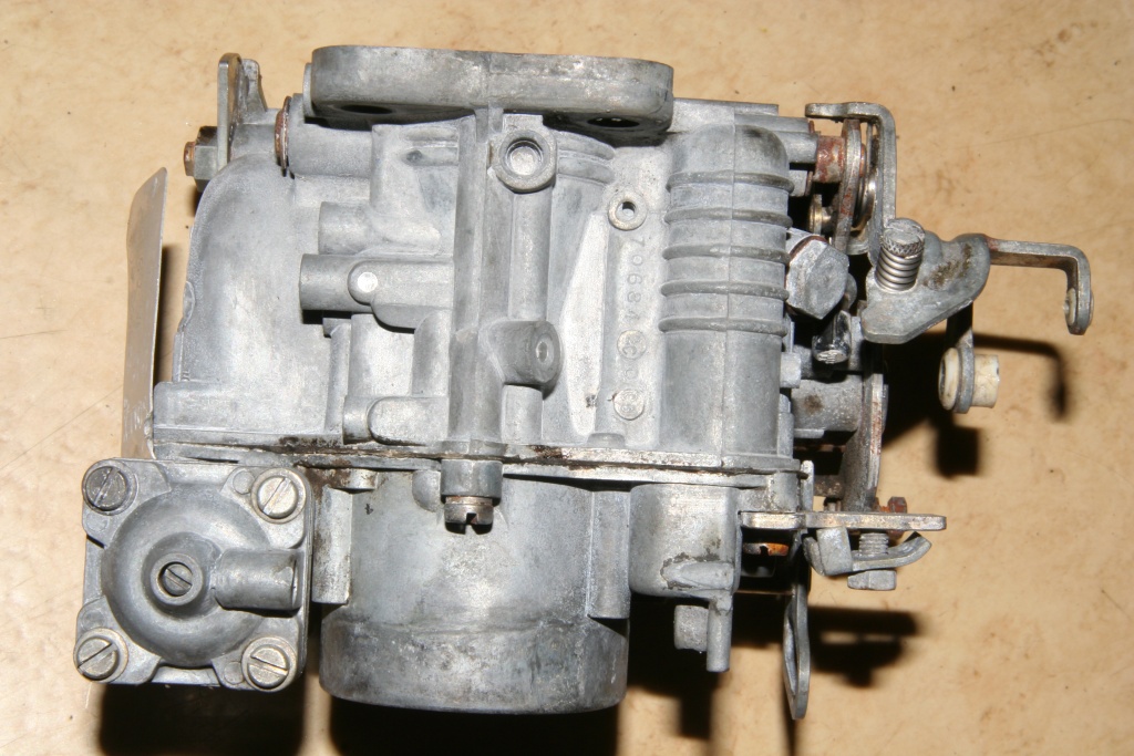 Backside. Left down you can see a vacuum actuator. More about this device is written down below. 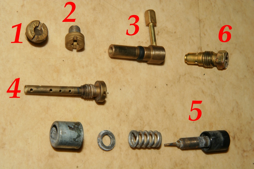 The nozzles. For cleaning you should never use needles or something like that, since the diameters will be expanded! Use compressed air to eliminate contamination. 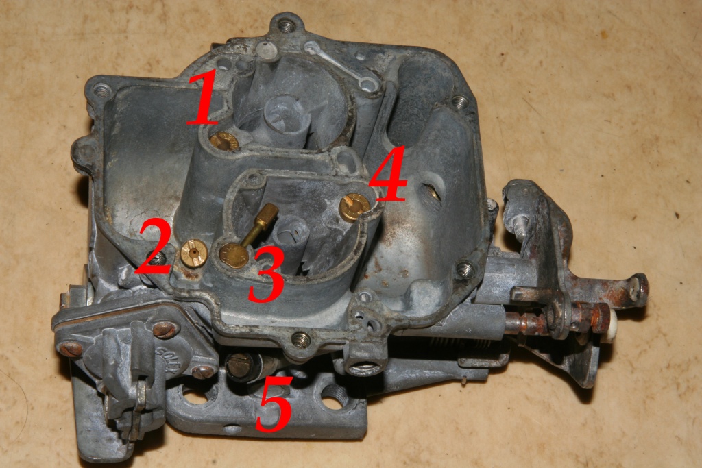 The nozzles in the inserted condition. The nozzle needle (5) whole turn in (NOT very tighten -the needle could be deformed) and then unscrew 3 1/2 tournaments. It is for adjusting the CO-concentration (emission inspection). All other nozzles are screwed in completely.  The floater. This is swivelling fastened to a brass axle (1), it can be disassembled with the help of a small nail. The floater closes the valve (2) when the correct fuel level is reached and interrupts thereby the further fuel supply into the Carburetor.  The distance from the center of the flotation chamber to the edge of the housing should amount to on both sides 19mm. 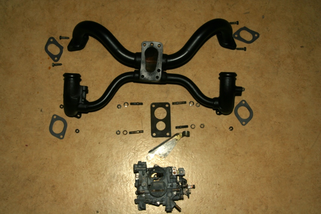 The carburetor is fastened on the manifold spider with four screw bolts. The two longer are bolted in front, those shorter in the back. The screw bolts are of the quantity M8, to which nuts for wrench width 13 are normally used. At least at the front fastening spots these nuts do not fit however. Here special M8 nuts with wrench width 12 are used! When assembling do not forget the plastic spacer plate (picture center). When fixing the bolts of the carburetor-spider on the engine block, it should lay flat on all four corners. Otherwise remove the cylinder head covers and loosen the bolts of the cylinder heads! Now fix the spider with 19Nm and tighten the cylinder heads with the correct torque again. In the first stage with 5 - 10Nm, in the second then finally with 20 - 23Nm. The order is up front, back up and then down. Finally the valve clearance has to be adjusted! 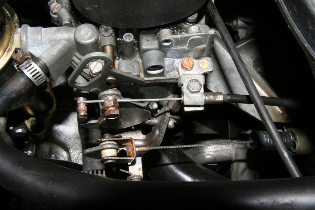 For control the carburetor has the Choke (1) and gas cable (2). The full acceleration position should be reached, when the accelerotor pedal is kicked down completely and not before that! In this case tension lies on the axis of the carburetor flap with completely kicked down pedal, whereby this will destroy the axis. The consequence is a clamping carburetor flap. Engine idle is adjusted with the help of the screw (3). This should be as low as possible, but not so low that the engine runs noncircular or vibrates strongly. 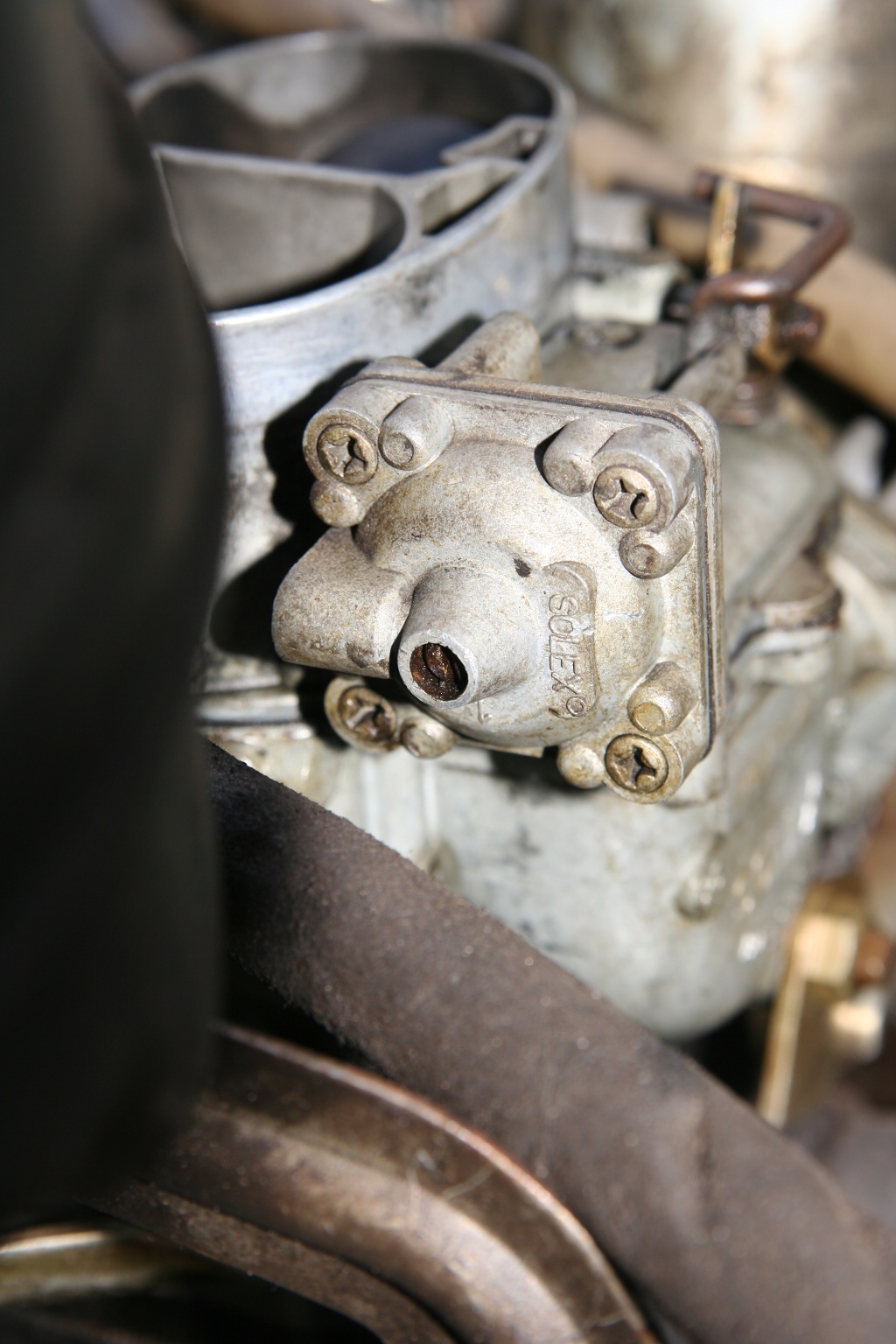 The vacuum actuator at the installed carburetor: This device opens the choke slightly when the engine starts running (cold starting process). So the air-fuel-mixture is adjustet to less fuel when the engine runs. Take a closer look at this component, when your engine does not start propperly. Maybe it is loosened or came off completely. 4 screws fasten the component. The central screw is for adjusting the vakuum actuator. 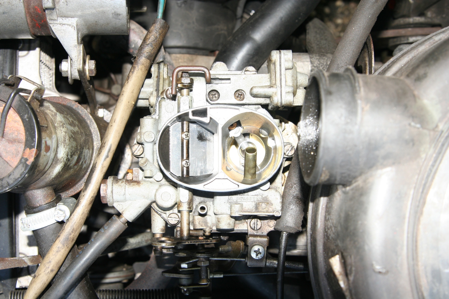 To adjust the vacuum actuator you have to pull the choke (=carburetor shut). 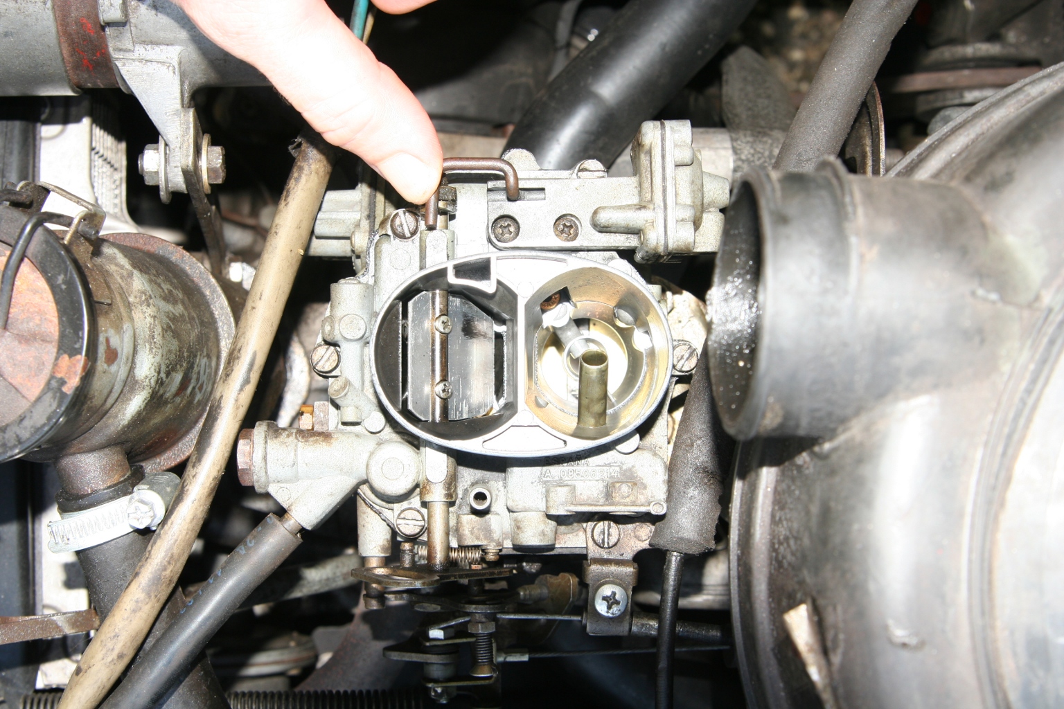 Now push the hook to the vacuum actuator. Now there should be a gap between 1.5 and 2.0 mm. Back to engine + gear Forward to breakes |