|
|
Back to pedals Forward to exhaust After the pedals, the mechanical levers are assembled: The gearshift lever is fixed by a pin at the lever of the gearbox inside the engine compartment and by a self locking nut (M6, wrench size 8mm) at the passenger compartment. After unlocking both attachments, the lever can be pulled out to the inside. 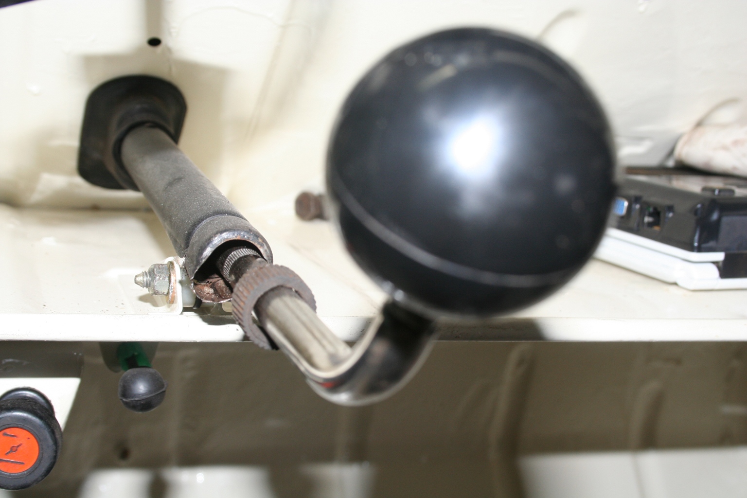 Don't lubricate the gearshift lever, just clean it with a dry rag! Oil destroys the rubber inside the guide tube. Somewhen it slips out and sooner or later the very thin-walled guide tube gets destroyed, too... 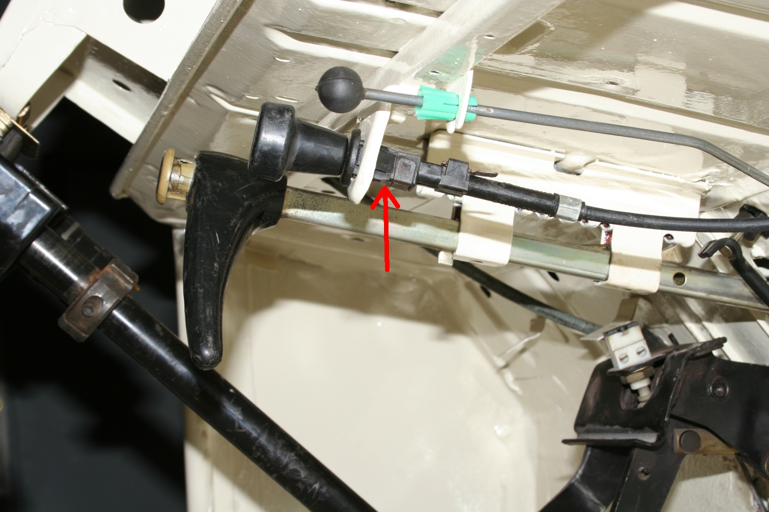 The lever of the handbrake can be pulled out to the inside after unlocking the pin at the engine compartment. The bowden cable of the cocke has to be unlocked at the carburetor inside the engine compartment. Then you must press together the plastic clamp (red arrow) to be able to pull out the mechanism. The lever controlling the airflow to the windshield has to be loosened inside the engine compartment and can be pulled out to the inside afterwards. 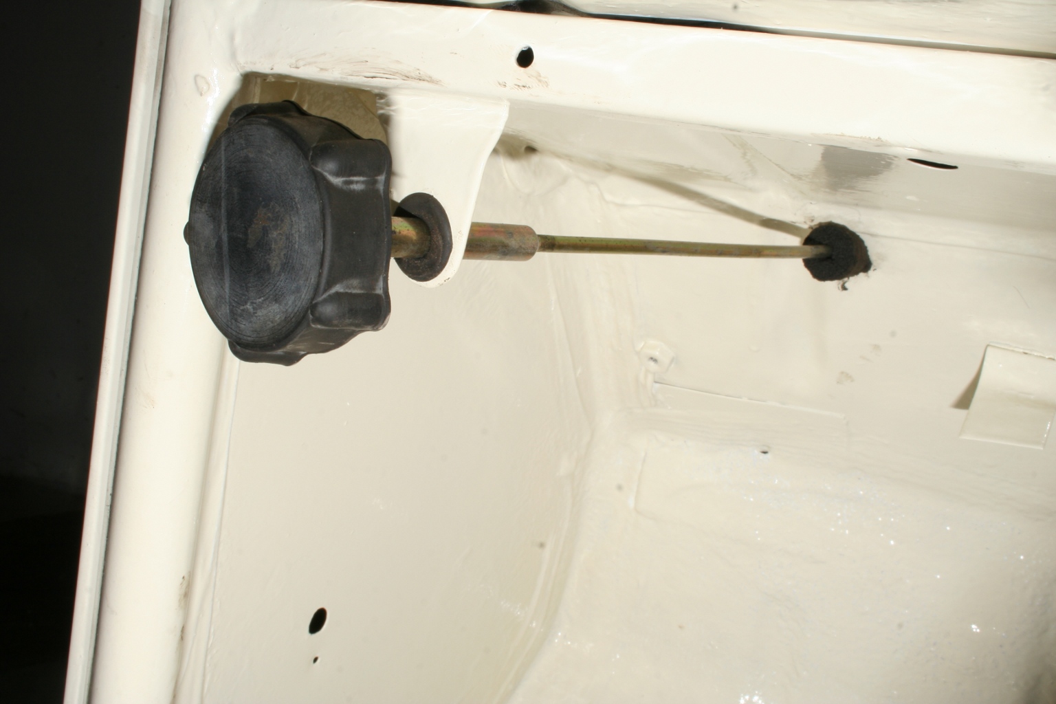 The leverage of the headlight range adjustment can be unscrewed and pulled to the inside after loosening the splint pin at the engine compartment. 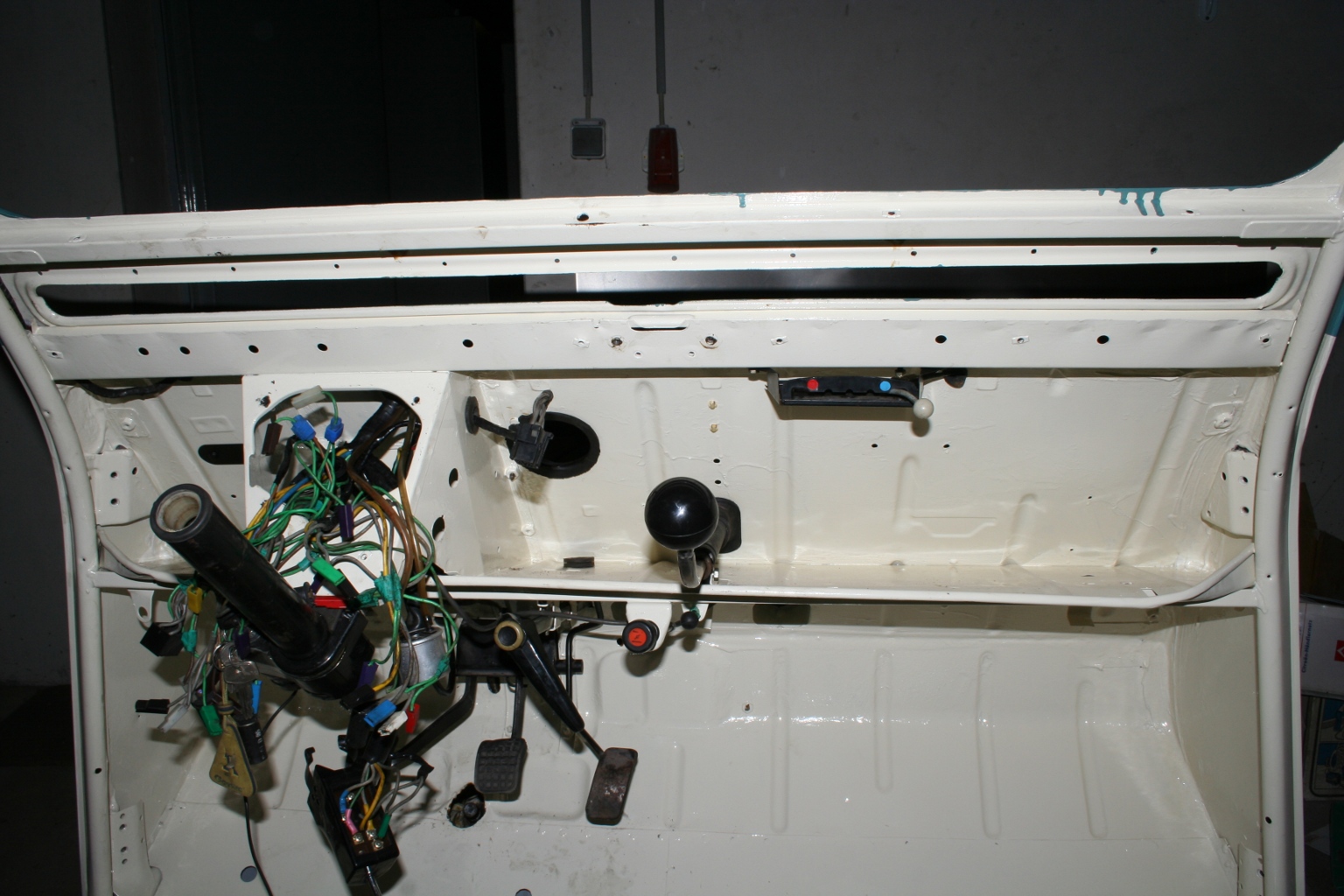  The ventilation flap is fixed at the sealing rubber, functioning as a hinge at the same time. The trim strip contains the screws for the attachment. Press ventilation flap and trim strip from the outside and... 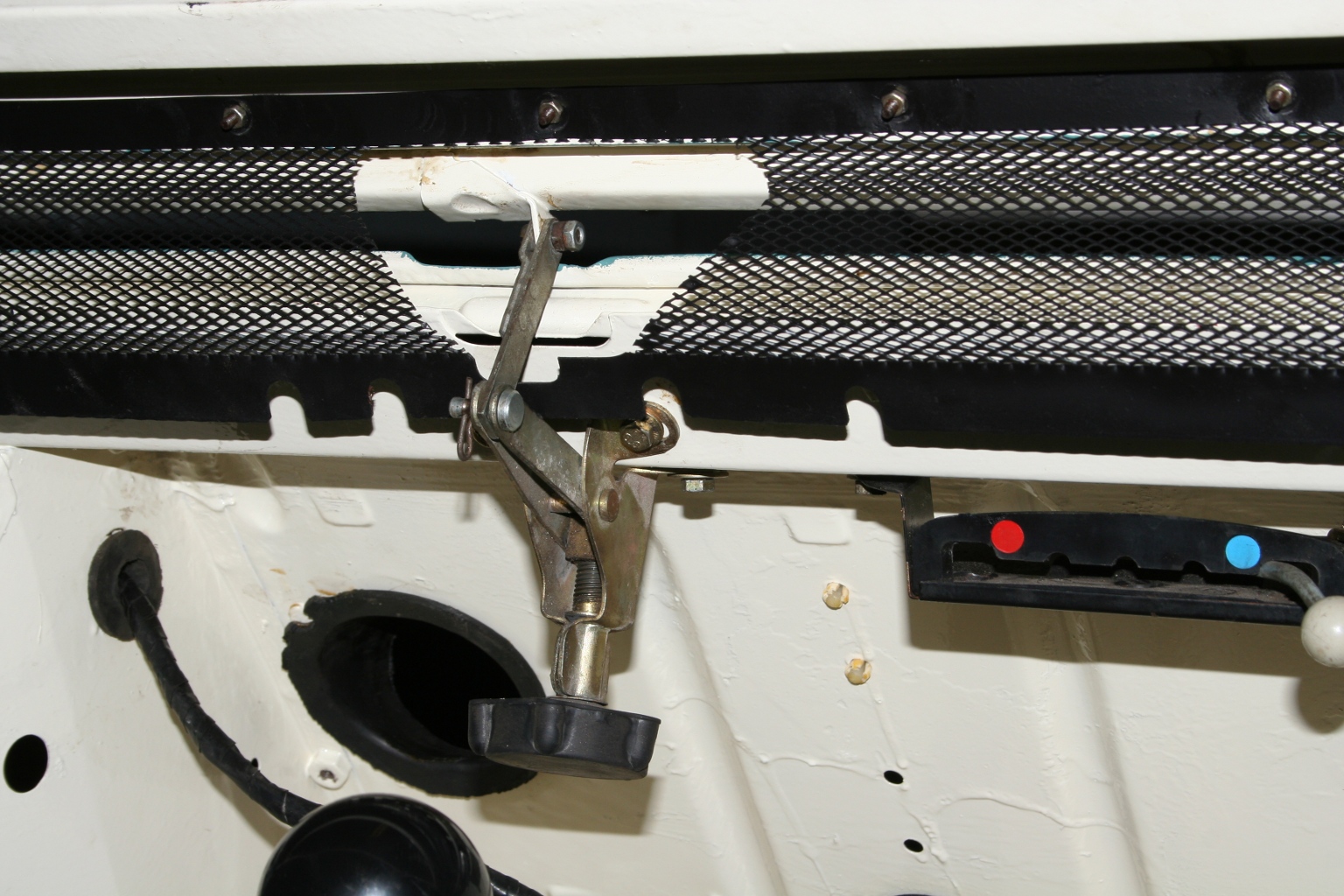 ... the protective grid from the inside at the bodywork. You can fix the parts with the help of the little screw nuts by now. 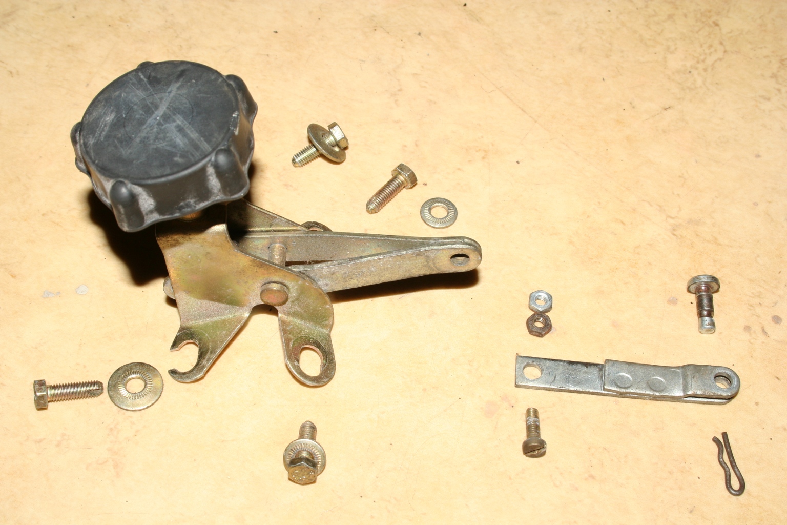 The mechanism for actuating the ventilation flap is fixed by 4 nuts M5 (wrench size 8mm). 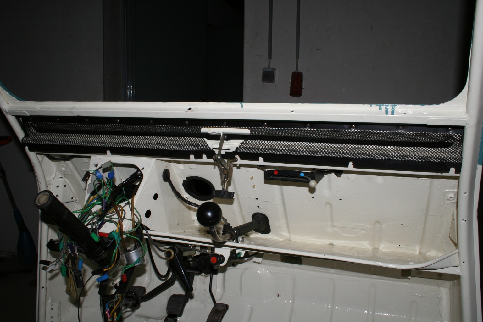 That's what it looks like in full view. 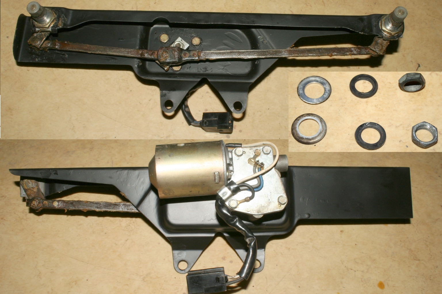 I greased the leverage of the windshield wipers well before assembling. 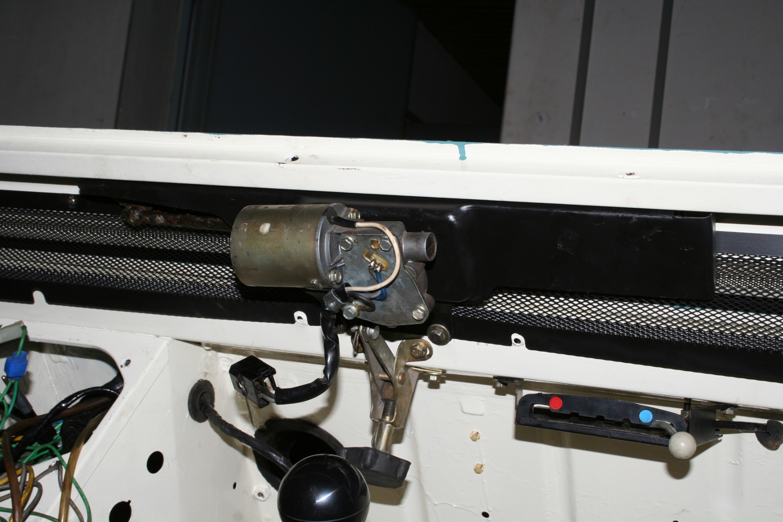 Now the mechanism can be fixed by two screws M5 at two mounting links. 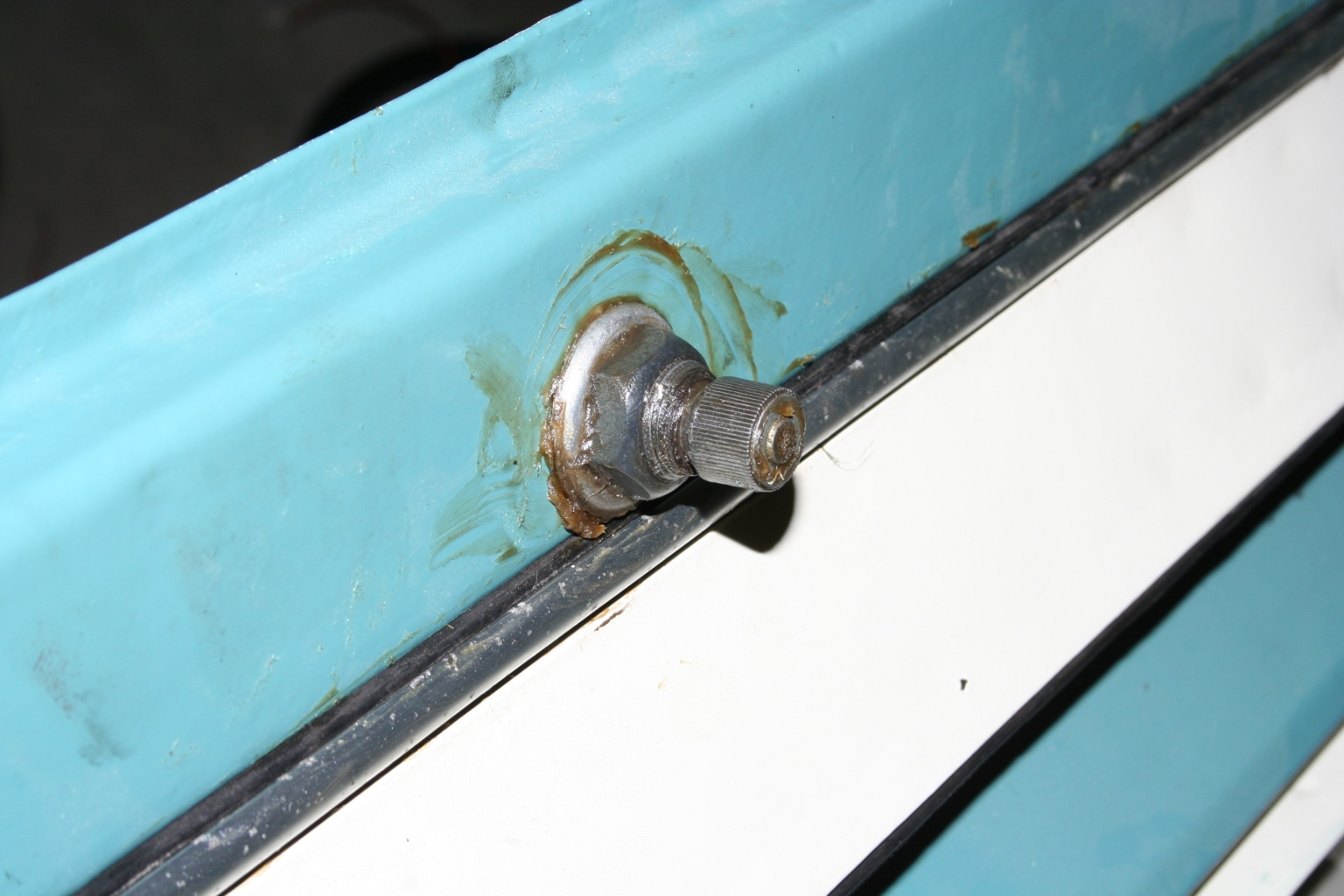 At the outside the mechanism is fixed at the axis of the wipers. I greased the parts very well (Mike Sanders grease) to avoid the penetration of water! 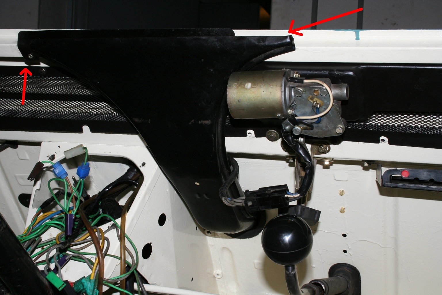 The air deflector for the wind shield has to be inserted into the sealing of the fire wall and it is fixed by two sheet metal screws. 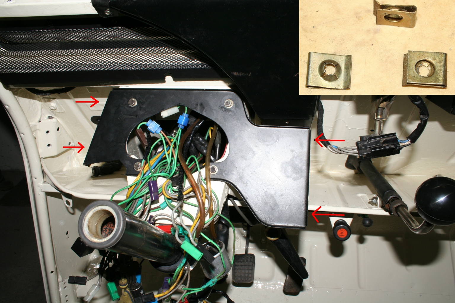 The speedometer is fixed at a holding plate. Four special mounting nuts are at the places marked by the red arrows.  Five sheet metal screws + grommets are used to fix the speedometer. 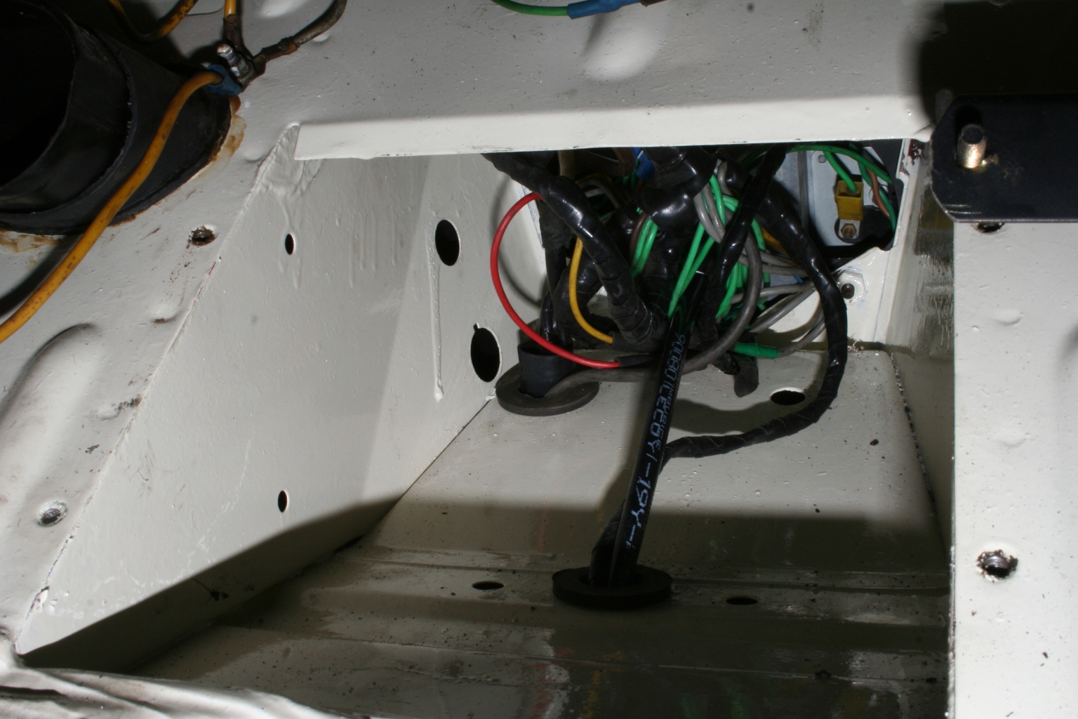 After removing the battery holder, some of the cables and the axle of the speedometer can be reached without having to remove the dashboard. 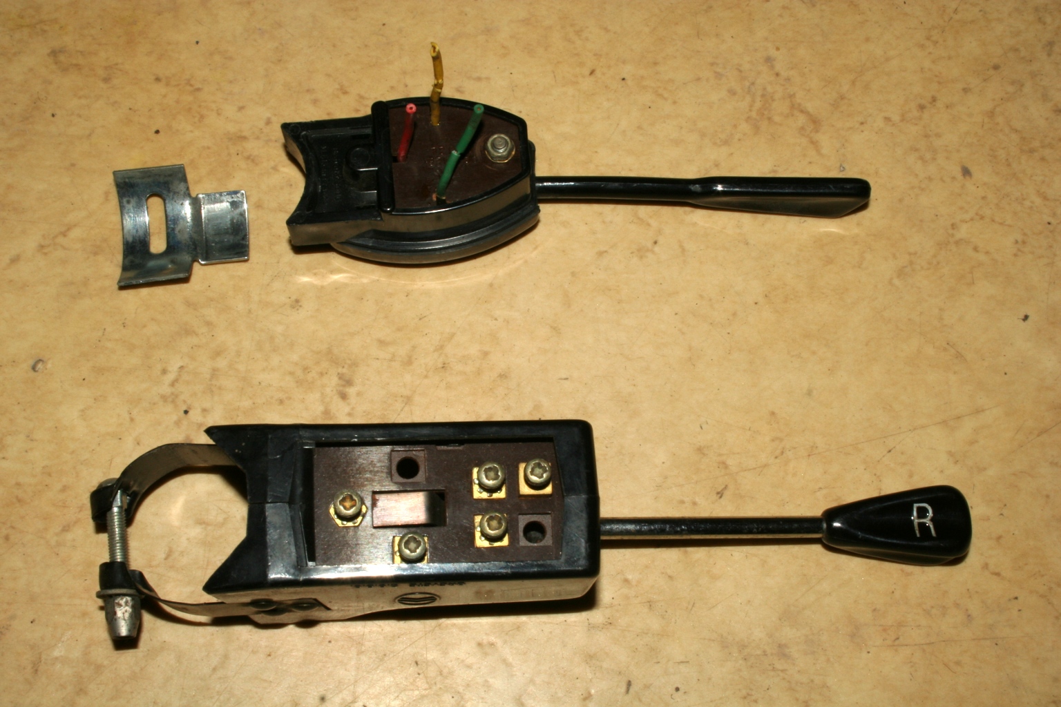 Turn signal and multifunctional lever are fixed by a clamping piece. The attachment of the turn signal lever is clamped and the lever can be clipped on this attachment. 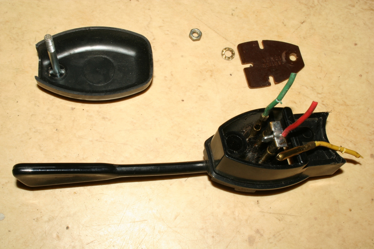 The cables of the blinker can be pulled out with their pin after opening the housing (yellow cable).  Opened blinker, view from top.  Mounted levers. 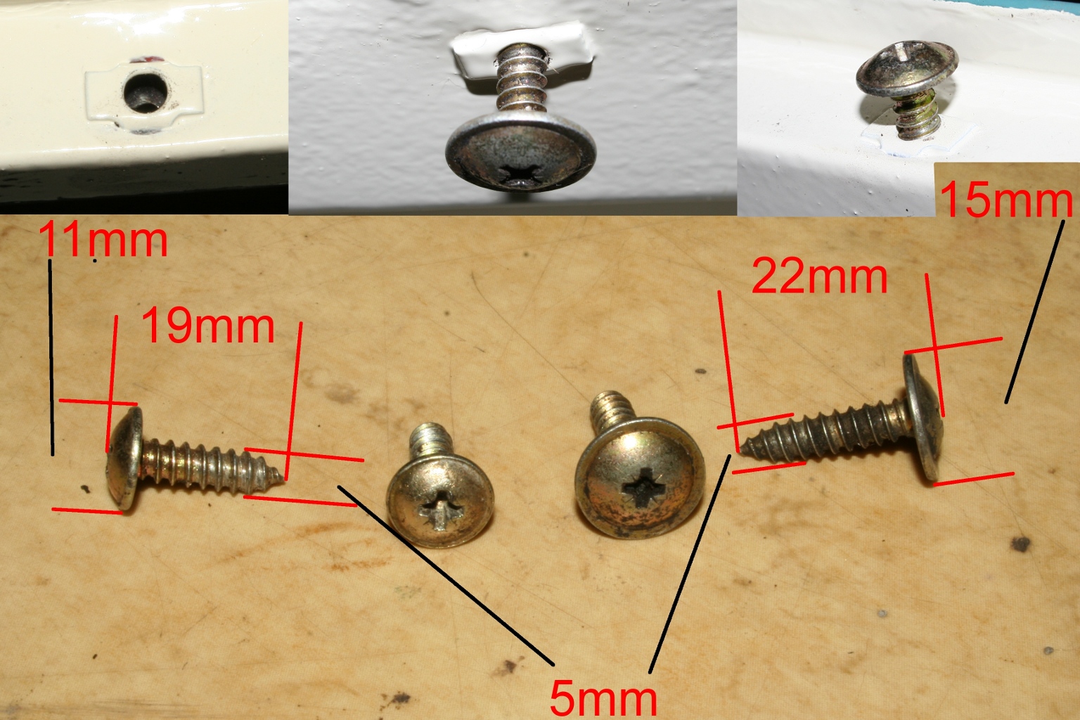 Those metal sheet screws fix the upper cover of the dashboard. 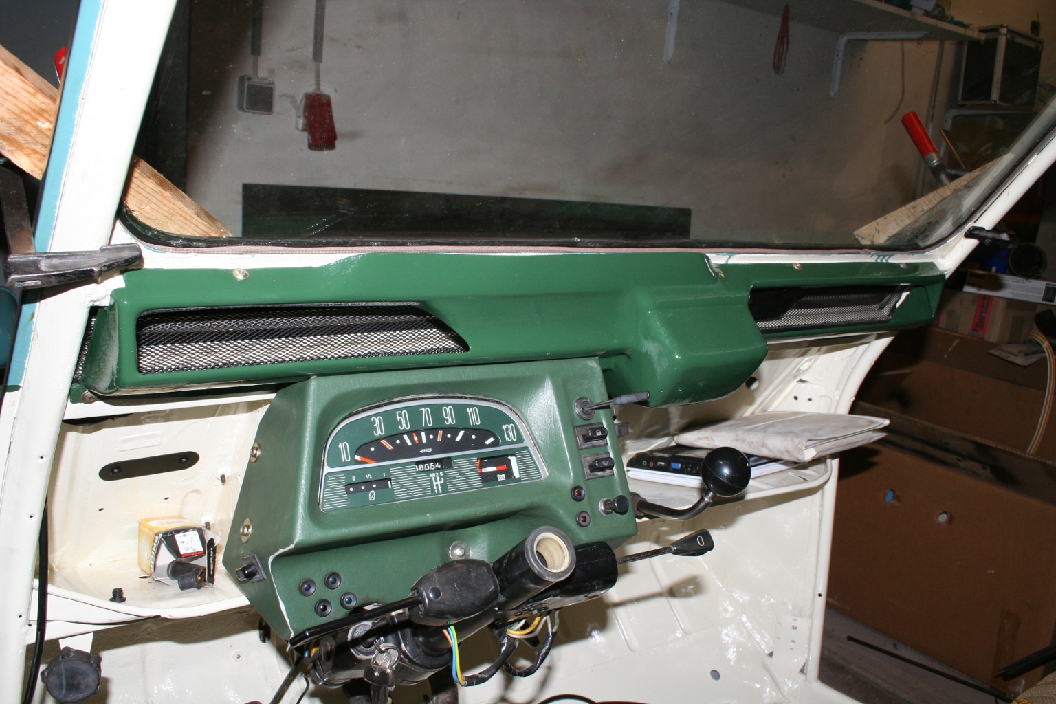 To assemble the cover of the dashboard I had to remove the speedometer unit once again... ....hence assemble this device BEFORE assembling the speedometer unit. Because of the fact that I had acquired a beautiful old speedometer at a jumble sale the replacement could be done at this step.  It took me a whole day of work and three attempts until the steering wheel was covered with imitation leather. ...to be continued... Back to pedals Forward to exhaust |