|
|
|
Back to electronics dashboard Forward to rear electrics Fasten the wires in the engine compartment carefully and protect them of the hot engine parts. Cable fires already grilled more than one duck (yes, Karin?). 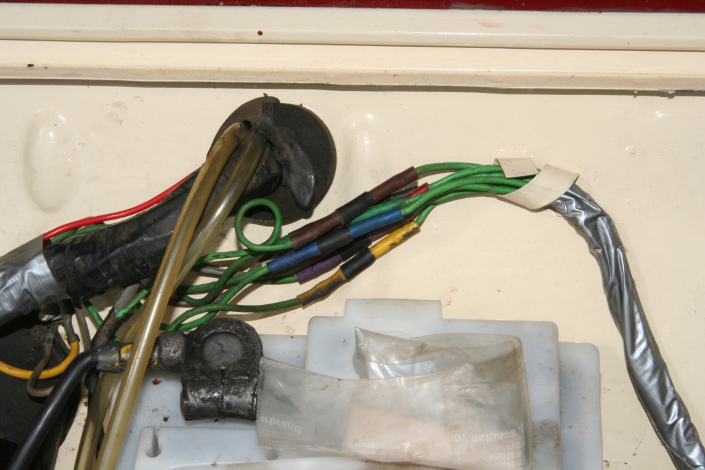 The first branching in the engine compartment is the connection to the rear wiring harness. The allocation is clear here, plugs and socket possesses the same colour codes. 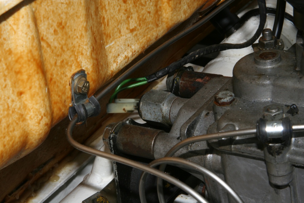 At the same place branch the plugs for the switch of the backup light. It's located at the rear of the gearbox. Right above in the photo the screw connection of the mass cable at the gearbox, which leads to to the battery, can be seen (see also further below). 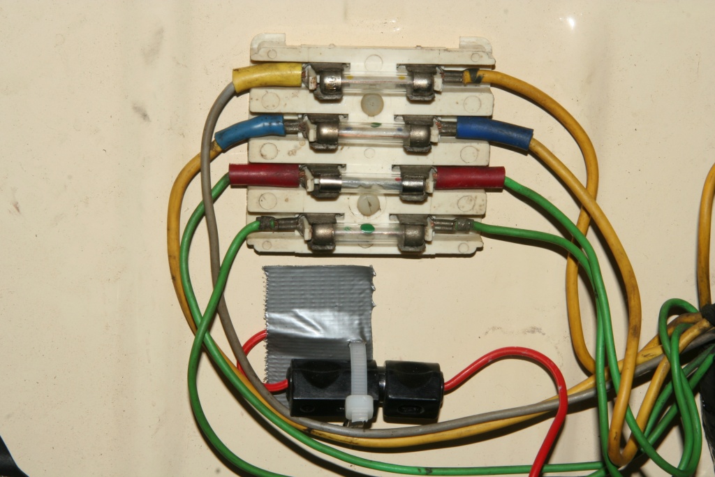 Here are the connections of the fuse box. The fuses from top to bottom: Grey cable with yellow marking - 16A - continuous positive, stop light, warning lights, interior lighting. Yellow cable with blue marking - 10A - ignition positive, windshield wiper, turn signal, fuel gauge, brake fluid control light, Choke control light, voltage control display, oil control light, current generator, back-up light. Green cable with red marking - 10A - parking light right, taillight right. Green cable without marking - 10A - parking light left, taillight left, dashboard light. Underneath the fuse box an additionally fuse is attached for radio, clock and other consumers at the interior (air-conditioner, electrically adjustable mirrors, on board computer, Champagne cooler, free speech mechanism mobile phone etc.). 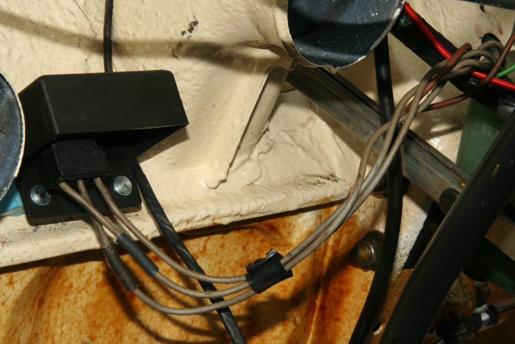 The voltage controller follows, here the electronic variant (the original one is here). The function of this construction unit is it to switch off the generator when reaching the battery charging voltage of 13,9V (14,5V with the original electromechanical variant) or to connect again with smaller voltage. 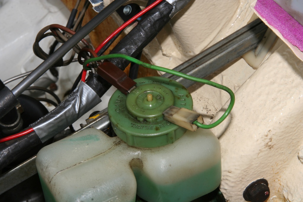 At the same place as the voltage controller branch off the contacts for the warning switch of the brake fluid. 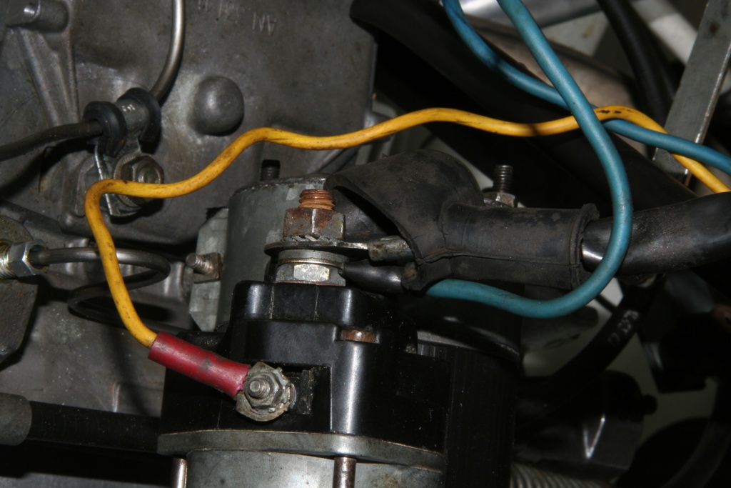 Next you see the starter here. From the wiring harness a bolt connection leads to the magnet switch (yellow cable), which is turned on by the starter lock. Directly at the starter the positive terminal of the battery is connected (see further below) and positive voltage for the wiring harness is mounted (blue cable). 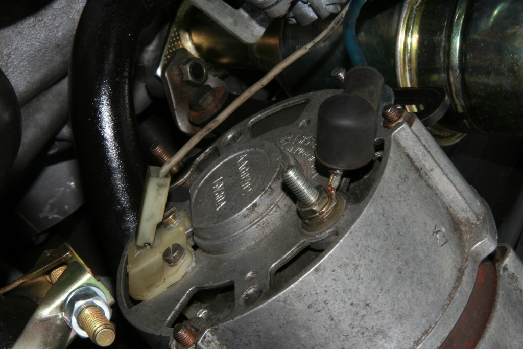 After that branches the connection for the generator. The screwing contact is the positive, the plug contact is the excitation cable. 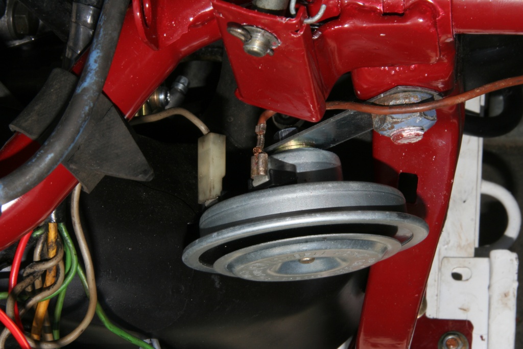 At last we see the connections of the headlight carrier. Here the horn. The mass return of the original horn is the attachment, the version illustrated here possesses for an additional connection (brown cable). 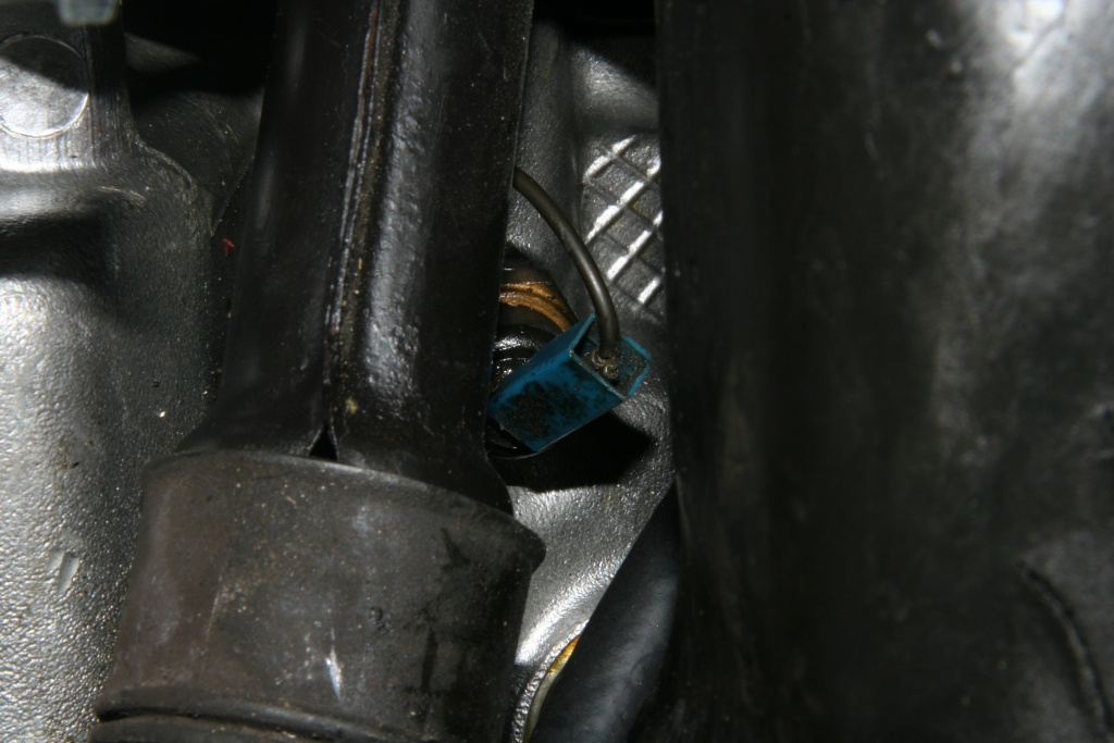 The oil pressure switch. It is above the oil pan on the driver's side. The connection with the wiring harness takes place by an extra cable, which is led upward together with the cable of the ignition in the fan cage. 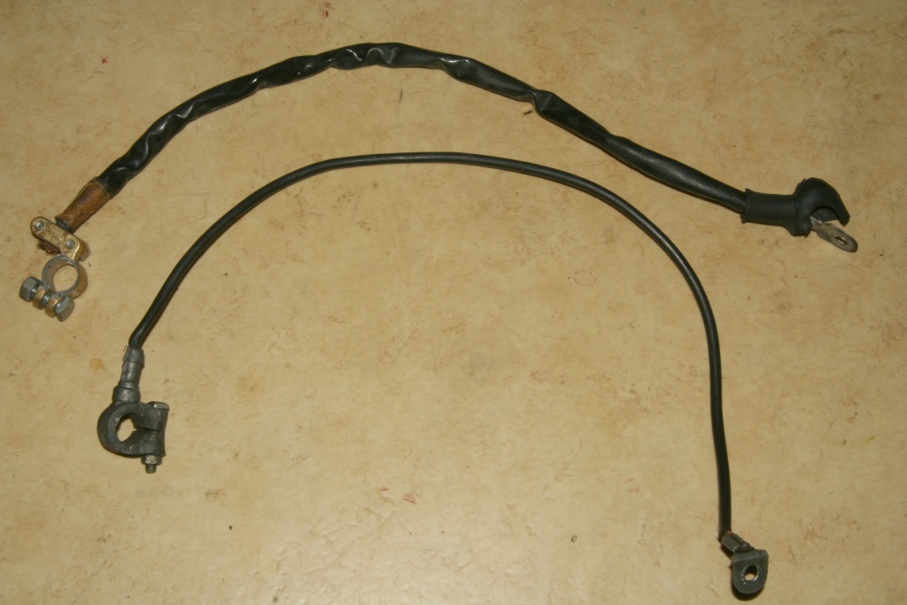 The cables with the terminal clamps. The positive terminal leads from the battery to the starter (picture above), the negative pole (mass) of the battery to the gearbox. 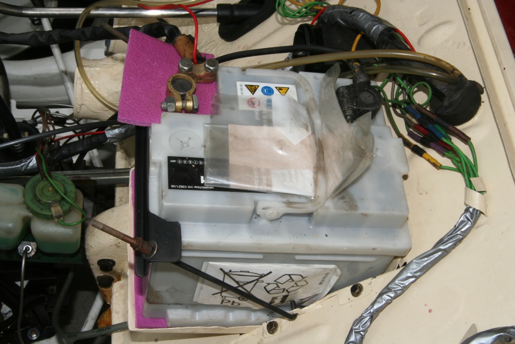 The battery in inserted condition. 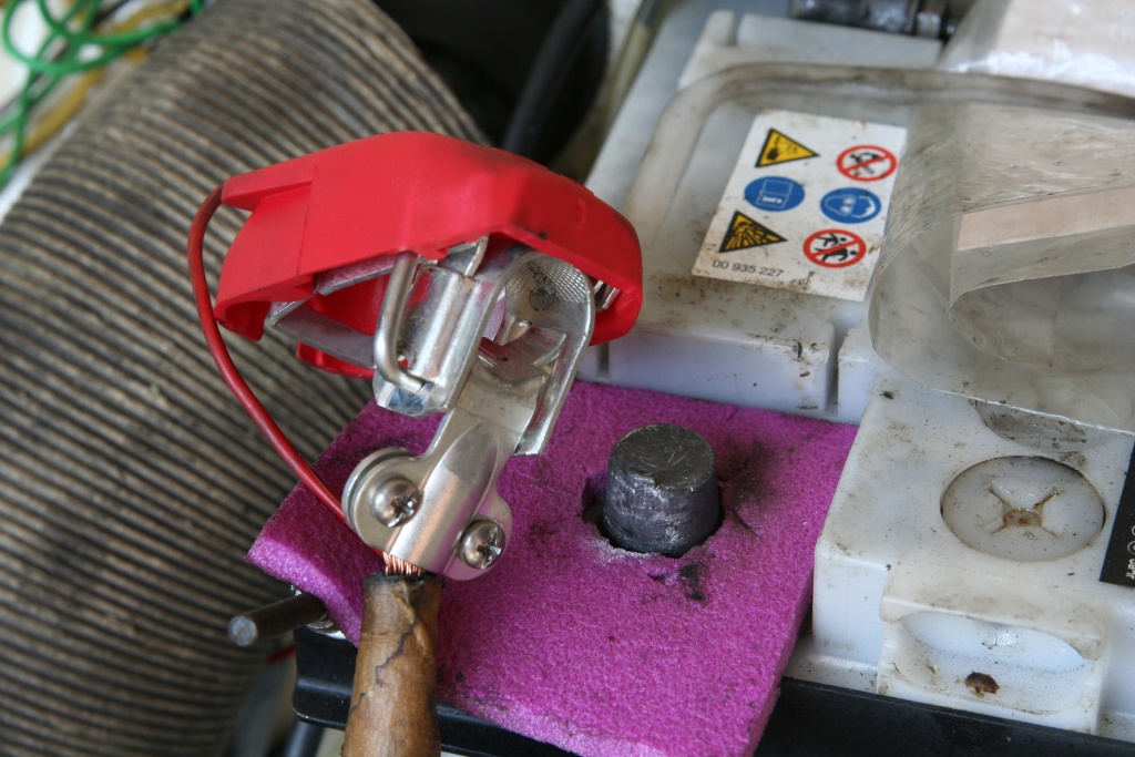 For the positive terminal of the battery I've bought a quick-locking mechanism meanwhile. So I can turn off voltage quickly, when the car is parked for a longer time. Back to electronics dashboard Forward to rear electrics. |